
The humble Belling-Lee UHF plug is widely used in Europe2 as a TV and FM connector, commonly known as a TV aerial plug. The correct method of wiring isn't obvious, and with digital terrestrial televison demands are being made of this connector that were never envisaged by the Enfield Belling Lee company in 1922.
Indeed I wired many of them as a student interested in electronics and on through the time while I was a broadcast engineer. The imperfections of the methods I had been shown were not a great issue for domestic analogue TV service. Confusion seems to be rife - in looking at several hotel type SMATV headends there were many other ways of wiring this connector, and some of them gave more trouble than others. I even observed some heroic attempts to solder not just the pin but the body of the plug. Considering that is usually made of aluminium, soldering it is not an easy thing to do...
DTT demands the right way, and I was set right by Tim Jenks of the CAI when I attended the CAI SMATV design course. So here it is - my interpretation of the definitive CAI approved method of wiring a Belling-Lee UHF plug to recommended WF100 (or CT100) 75ohm aerial cable.
You will need:
The usual incarnation is an aluminium bodied plug, which can be dismantled by grasping the knurled parts and unscrewing the two aluminium sections. There are plastic-topped variants which have the same innards.
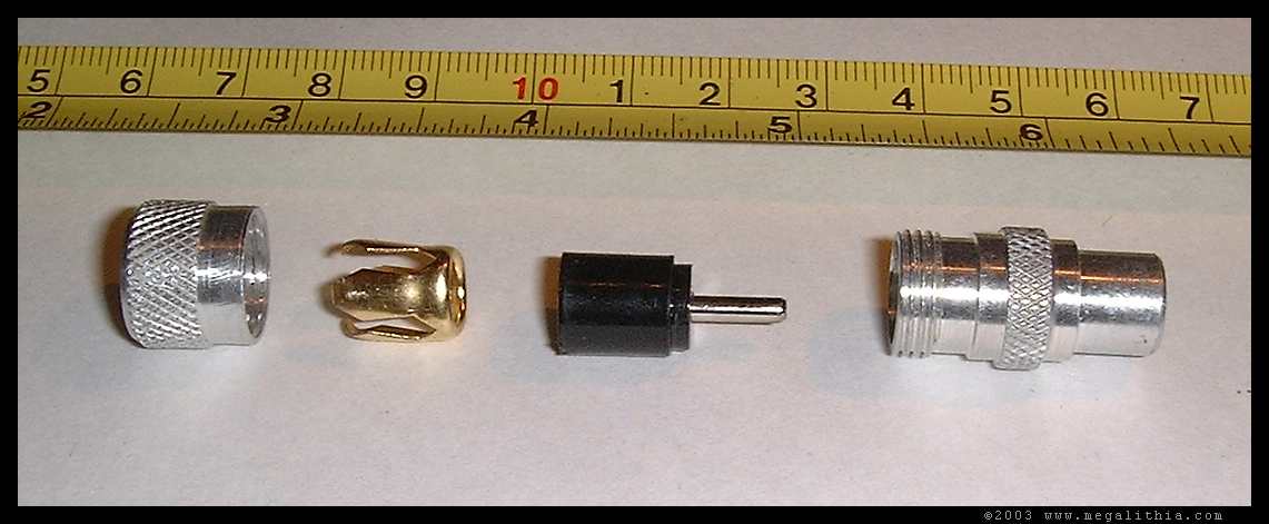
Fig 1 - the four parts of the connector
once you have it apart, first take the left hand part in the above photo and slip it over the cable, shown in stage 1.
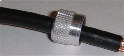
Stage 1: cap onto cable
The next stage is to skin 3cm of outer insulation from the end of the cable with the Stanley knife, taking care not to cut into the metal parts inside. The insulation is only about 1mm thick.
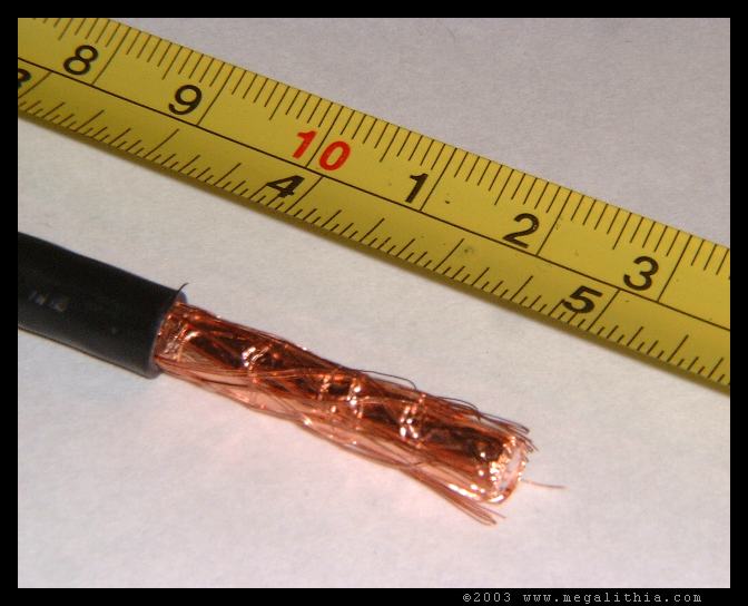
Stage 2: 3 cm of outer insulation removed.
Observe the cable has a copper tape which is overwound with a knitted braid of copper cable. It is the tape that give this cable its excellent shielding properties. If you are still thinking to yourself I can get away with my brown TV coax for DTT read the cable section. Now take the brass or nickel claw device second left in fig 1 and carefully slide this over the tape and braid. This is fiddly, usually involving rotating the claw as you push it back. Tape and braid must pass through the hole in the claw.
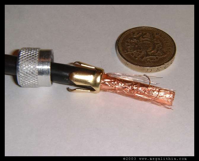
Stage 3: the claw pushed back
The next stage is to push the claw right back against the black insulation and comb the braid out so it is fanned over the claw as shown in Stage 4
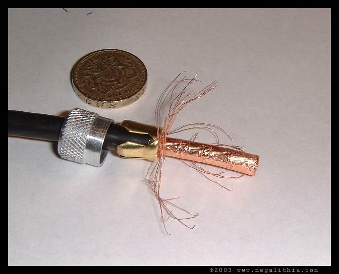
Stage 4: the braid fanned over the claw
Now peel the tape back from the end of the cable to the claw - you should just be able to tear it back1. Should look like this -
Stage 5: tape removed
Now trim all but about 3mm of the white foam insulation (clear-ish honeycomb polythene if using CT100) back to expose the inner conductor. Take care not to nick the inner conductor, as otherwise that is where it will snap off after a year or so of cable movement...
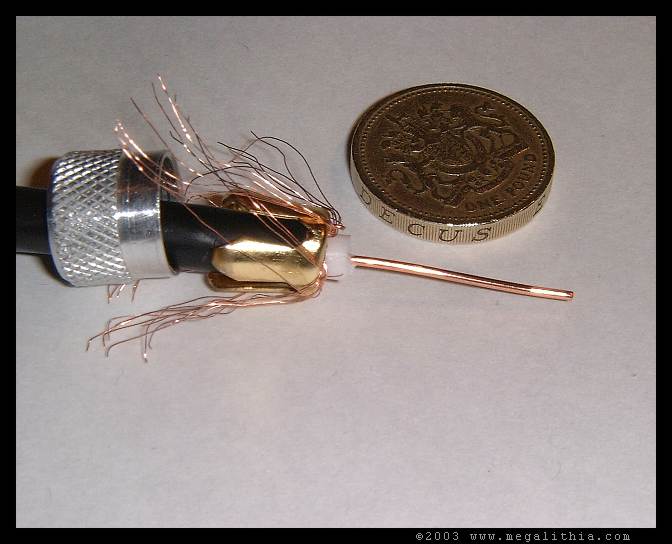
Stage 6: inner conductor exposed
Now for the next stage, there's a right way and two wrong ways to do it. If you are going to solder the inner conductor. you have selected the right way. If you absolutely insist you can't solder the inner conductor, then at least bend it about 10 degrees 0.5 cm from the end so it makes contact with the pin when the plug is freshly made. That will last you about 6 months to two years of acceptable contact in practice. If you don't bend it all bets are off - you are about to make a scratchy, intermittent connection whatever you do. The choice is yours.
You naturally take pride in your work and so you're going to solder this. In that case don't bend the inner at all.
Take the plastic item which holds the inner pin of the connector, and slide this over the inner conductor. In the particular connector I selected here, this is black, but in most of these connectors I've seen the plastic is milky nylon.
Stage 6: slide pin over inner wire
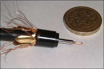
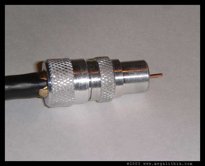
Some of the inner wire should stick out from the pin. That is fine. Now slide the remaining metal part over the assembled plug.
Stage 7: slide remaining metal part over assembly
Push this right back as far as it will go, and then comb out the braid over the lip of the aluminium part at 90 degrees to the cable all round.
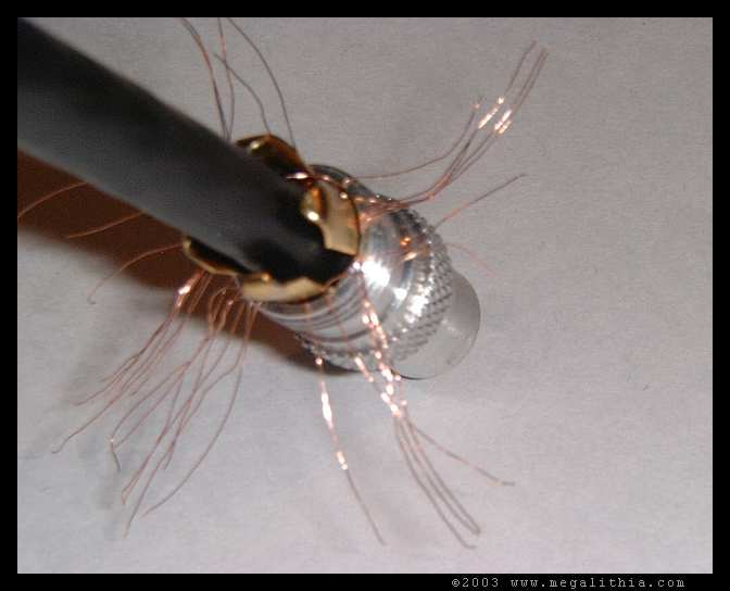
Stage 8: Comb the braid out perpendicular to the cable
Now do a haircutting action - trim the braid as close to the aluminium part as possible and smooth what's left back along the cable. There is a temptation to use scissors here that should be resisted - leastways if you want to use the scissors again... This is fiddly using wirecutters. You want to avoid stray bits of braid extending past the claw out of the top of the plug or catching in the thread as you screw the top on in the next stage.
Stage 9: Braid trimmed back
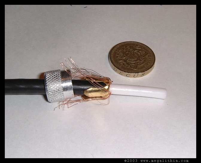
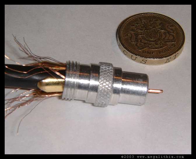
Take the aluminium top of the plug which was the first part slid onto the cable and screw it down onto the plug over the claw, which will be compressed to grip the insulation of the cable as you can see on the left of the photo below.
Stage 10: top of plug screwed onto plug body
All the remains is to solder the centre. Unfortunately the plastic holding the pin is made of a low-melting point plastic. Touch the soldering iron to the protruding centre of the cable and not the pin - the solder will wick up into the pin as it melts but you get a few seconds more before the plastic melts.
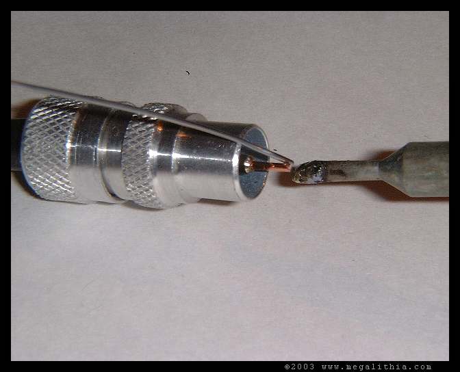
Stage 11: soldering the centre pin
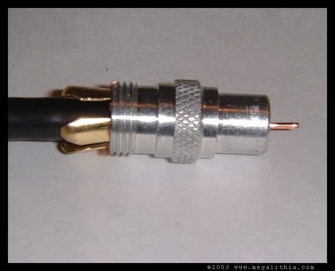
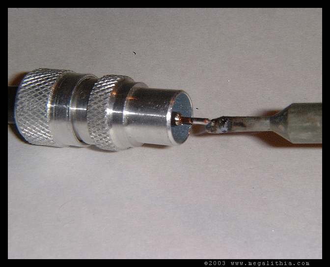
You should end up with something that looks like this -
the soldered pin
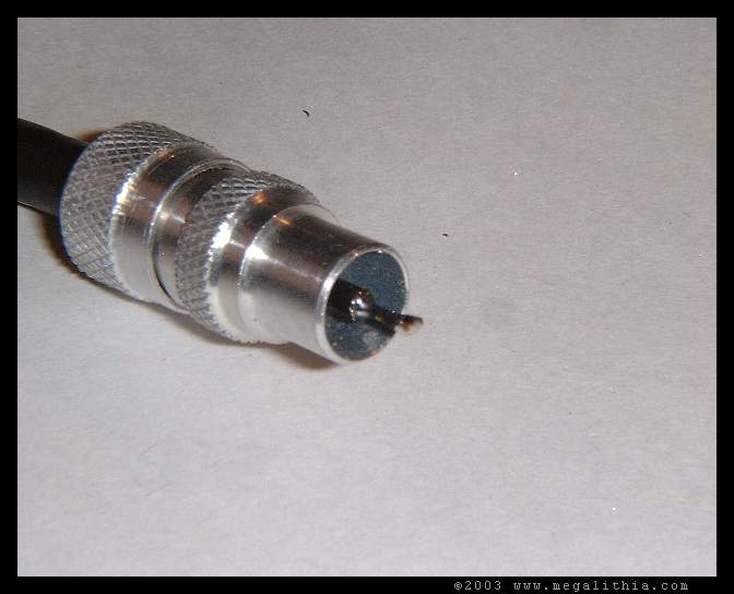
All that remains now is to trim off the excess wire sticking out of the centre pin with wire cutters and you have one made up Belling-Lee connector
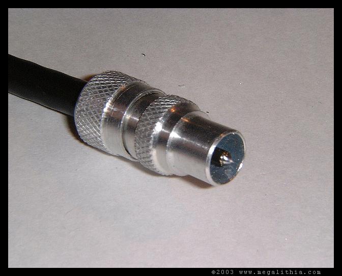
Stage 12: trim off the excess wire sticking out of the pin and you are done
Selecting and siting your TV aerial
Why DTT is different from an analogue install
![]()