
The balanced signal cables carry the +ve rail and the screen the -ve. Unlike plug-in-power, this is specified in a standard (part of IEC 61938) which also specifies the voltage tolerances and maximum current drains (10mA). This is not always observed. Most systems get the voltage right, but older gear may only be able to deliver 2mA (an older version of the standard). The M-Audio Microtrack is notable for an out of spec 30V phantom power voltage[1,2].
One of the problems you may have is wiring this to an unbalanced input such as a minidisc recorder. The first problem you have is that the MD recorder doesn't put out +48V anywhere, so you need an outboard phantom power unit.
You can buy these reasonably cheaply - for instance the Thomann Millennium I have is 12V powered, costs about £25 from Thomann (2007) and looks like this -
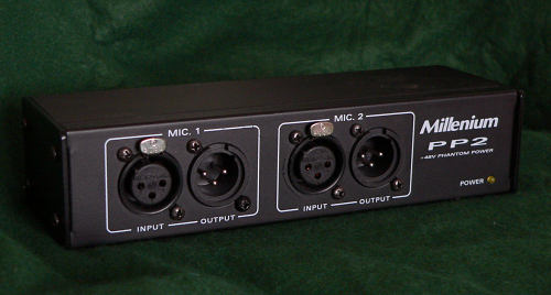
Thomann Millennium P48 power supply
You can DIY this but it is hardly worth it. The schematic is easy enough but construction is tedious - and it is difficult to beat the readymade price unless you have a well-stocked junk box and a fondness for metal-bashing.

Fig 1 - Phantom powering schematic (one channel)
You can use 6.8k resistors, the matching requirements are not as critical as for a balanced output as you are going to unbalance the output anyway. Six 8.4V NiMH batteries give 50.4V supply voltage (check your mic spec - the Sennheiser MKH40 is specified at 48V ± 4V). The commercial unit saves all this trouble.
You've now got a way of powering up your mics, but they are still putting out a balanced signal, possibly still with 48V on pins 2 and 3 relative to pin 1. There are two main ways of wiring this to unbalanced gear, each with their own pros and cons.
This is a low cost and reasonably high performance method, though you will pay by losing balance in the mic cable, with a corresponding increase in susceptibility to noise and interference.As well as losing the advantages of balanced working. you may take a loss of 6dB in signal voltage using this method, since you are not using the antiphase signal, halving the output for a given sound pressure level. Whether this happens will depend on the exact details of the microphone circuit.
The MD recorder won't appreciate the 48V phantom supply presented to its input, so a correctly polarised electrolytic capacitor of at least 100uF 63V working voltage needs to be placed in series. Unless, that is, you know categorically that your phantom power supply does not pass the P48 voltage on to the output, in which case you can replace the capacitors in Fig.2 with shorts.
Fig.2 Phantom to MD connection schematic. (green is left, red is the right channel)
Fig 2 shows the required connection, adapted from ref [3] - for the many mics nowadays that are electronically balanced[4]. You can usually tuck the capacitors into the female XLR line sockets to make this cable up. Wildlife sound recordists may consider whether a frequency response down to 20Hz is required, and could change the coupling capacitors to a lower value, while will help reduce the level of wind blast into the MD stages. The 22k resistors are there to bleed away the inital 48V charge when power is first applied. You don't want to dump this into the MD input stages when first plugging in. You should power the mic first unplugged from the MD, let things settle for a second or two and then plug in to the MD to be on the safe side.
A side effect of lowering the coupling capacitor value may be to raise the noise level at low frequencies (the preamp noise is damped less by the source impedance) so it needs to be evaluated. Some HiMD recorders eg the Sony MZ-NH700 already have a 0.1uF capacitor internally after the pip circuit, so they already exhibit a slightly rising noise floor at low frequencies, and therefore the 100uF capacitor can be lowered with little adverse effect on the LF noise floor.
Caveat Constructor
This works for me using a HiMD, phantom power unit and Sennheiser MKH
P48 mics. It will only work for P48 supplies and not for
T-powering. You
have to evaluate if it will work for you.In the
interests of the health of your gear you should evaluate your
constructional ability honestly - this is a simple circuit and if you
don't understand it you should not try and build it. It follows the
principles outlined in ref [1]
which is from a well
established microphone accessories supplier. If you follow the
schematic you should get the same result as me, but you should test
that
this meets your requirements.
At the very least you should
power the P48 supply up and test the 3.5mm jack before putting into the
MD
recorder to check the voltage on the tip and ring is at a DC level of
0V relative to the sleeve. That will catch any leaky or backwards
connected capacitors before
they have a chance to damage your recorder. Another good step
would be measuring the phantom voltage before you plug the mike in to
make sure
it is 48V on both pins 2 and 3 of the XLR relative to pin 1 with the
phantom to MD cable plugged in but not connected to the MD.
NB I'm not supporting this in any way and if you bend your
gear
with it then you have only yourself to blame!
An alternative to making up the cable above is the microphone transformer. Not as common a device as it used to be, you can purchase a step-up transformer which has a XLR balanced input and an unbalanced, usually ¼ inch mono jack. These often offer a selectable 1:1 or 1:100 impedance ratio. The 1:100 transforms the 150 ohm microphone impedance up to 15k, and at the same time give a useful 10x boost in output voltage[5], improving your recorder's noise figure by almost that much (the impedance ratio is the square of the voltage ratio). At the same time the transformer will properly balance the microphone input and use both phase and antiphase outputs of an electronically balanced mic (no 6dB loss). It will not be troubled by the 48V phantom power, will not pass that to the unbalanced side, and it is available off the shelf.
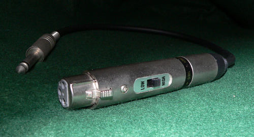
Microphone matching transformer
With so many advantages the transformer has a lot going for it. The main disadvantage is that transformers tend to distort the signal passing through them, losing sound clarity, and cheap transformers do that more than expensive ones. Vintage equipment used transformers widely, and the quality of the transformer had a large influence on the sound - giving rise to the adage "the sound is in the iron".
Transformers are worth considering, particularly if you can borrow one to try - you may be pleasantly surprised with simple signals without lots of low frequencies. A transformer can do a lot for your noise performance with low signal levels like wildlife recording, particularly if you are using a noisy preamp like an early MD recorder or a cheap (sub $1000) compact flash recorder. However, you must listen to what things sound like with and without the transformer (after matching signal levels to allow for the transformer step-up), in particular for a loss in clarity. With music a muddiness in low frequencies may also be evident.
If you can, you should disable the minidisc plug-in-power, if not place a series capacitor with the positive end towards the recorder to block it. Audio transformers hate DC passing through the windings - distortion increases and signal handling capability decreases.